Generac GP3300 Manual: A Comprehensive Guide
This manual, dated 02/09/2026, provides a detailed overview of the Generac GP3300, assisting users in maximizing product performance and understanding its features.
The Generac GP3300 is a portable power solution designed for a variety of applications, from camping and tailgating to emergency home backup during power outages. This user manual, current as of February 9th, 2026, serves as a comprehensive guide to ensure safe and efficient operation of your generator. It details everything from initial setup and component identification to maintenance procedures and troubleshooting common issues.
This generator boasts a user-friendly design, combining portability with reliable power output. Understanding its features and adhering to the safety guidelines outlined within this manual are crucial for maximizing its lifespan and preventing potential hazards. We’ve included a dedicated parts diagram for easy reference when servicing or replacing components. This guide aims to empower you with the knowledge needed to confidently utilize your Generac GP3300 for years to come, providing peace of mind and dependable power whenever and wherever you need it.
Safety Precautions
WARNING: Carbon monoxide is a deadly, odorless gas. Never operate the Generac GP3300 indoors or in partially enclosed spaces. Always operate in a well-ventilated area. Failure to do so could result in serious injury or death. Keep the generator at least 20 feet away from your home, windows, and vents.
Before operating, carefully read and understand all safety instructions. Ensure the generator is placed on a level surface. Never refuel the generator while it is running or hot. Allow it to cool completely before adding fuel. Keep children and pets away from the generator during operation. Avoid overloading the generator; adhere to the wattage limits specified in this manual. Always disconnect all appliances before performing maintenance. Use appropriate extension cords rated for outdoor use. Regularly inspect the generator for damage and address any issues promptly;
Unboxing and Initial Setup
Carefully unpack the Generac GP3300 from its shipping container. Verify all components are present, referencing the parts list included in the packaging. Inspect the generator for any visible damage that may have occurred during transit. If damage is detected, contact your retailer immediately.
Before first use, add the supplied oil to the correct level, as indicated on the dipstick. Do not overfill. Ensure the air filter is clean and properly installed. Locate the fuel shut-off valve and confirm it’s in the ‘OFF’ position before adding fuel. Add fresh, unleaded gasoline to the fuel tank, leaving some space for expansion. Double-check all connections and ensure the generator is placed on a stable, level surface in a well-ventilated area before attempting to start it. Familiarize yourself with the location of all controls.
Component Identification
The Generac GP3300 features several key components crucial for operation. The Generator Body houses the engine and alternator, providing a durable protective casing. The Recoil Start Mechanism allows for manual starting, even without a battery. Familiarize yourself with its pull cord and choke lever.
Output Receptacles are vital for powering devices. The GP3300 includes 120V outlets for standard appliances and a 12V DC outlet for charging batteries or powering compatible accessories. Locate the Fuel Tank and Oil Fill Cap for refueling and maintenance. The Air Filter Housing protects the engine from debris. Identify the Exhaust Port, ensuring it’s directed away from flammable materials. Finally, understand the function of the Circuit Breakers, which protect against overloads.
Generator Body & Controls
The Generator Body of the GP3300 is constructed from a robust, impact-resistant polymer, designed to withstand outdoor conditions and provide long-lasting durability. Key Controls are strategically placed for easy access. The Power Switch enables or disables the generator’s output. The Choke Lever regulates the air-fuel mixture for starting, particularly in cold weather.
The Throttle controls engine speed and power output, adjusting to the connected load. A Run/Stop Switch provides operational control, while the Circuit Breakers offer overload protection. Familiarize yourself with the Hour Meter, tracking runtime for maintenance scheduling. The Low Oil Indicator Light alerts you to insufficient oil levels, preventing engine damage. Understanding these controls ensures safe and efficient operation of your Generac GP3300.
Recoil Start Mechanism
The Recoil Start Mechanism on the Generac GP3300 provides a manual starting option when electrical starting isn’t available or preferred. This system utilizes a pull cord connected to a spring-loaded pulley. To initiate, ensure the Fuel Valve is open and the Choke Lever is in the appropriate starting position (refer to Operating Instructions).
Gently pull the recoil cord with a smooth, controlled motion. Avoid jerking the cord, as this can cause damage. Once the engine attempts to start, gradually allow the cord to retract. Repeat this process if necessary, adjusting the choke as needed. Proper technique minimizes strain on the mechanism and ensures reliable starting. Regularly inspect the recoil cord for fraying or damage, replacing it if necessary for continued functionality and safe operation.
Output Receptacles (120V & 12V)
The Generac GP3300 features multiple Output Receptacles to accommodate various power needs. It includes standard 120V AC outlets, designed for powering common household appliances and tools. These outlets are typically grounded for safety. Always ensure appliances are compatible with the voltage and wattage capacity of the generator.
Additionally, the GP3300 provides a 12V DC output, useful for charging batteries or powering 12V devices. A DC charging cable (often not included) is required to connect to the 12V receptacle. Never exceed the maximum amperage rating for either the 120V or 12V outlets to prevent overload and potential damage. Always disconnect appliances before refueling or performing maintenance. Proper use of these receptacles ensures safe and efficient power distribution.
Operating Instructions
Before operating your Generac GP3300, ensure it’s placed on a level surface in a well-ventilated area, away from flammable materials. Always check the oil level and fuel level before each use. Familiarize yourself with all controls and safety features; This section details the procedures for both Cold Start and Warm Start scenarios, outlining the necessary steps for successful ignition and operation.
Properly Connecting Appliances & Loads is crucial; never exceed the generator’s wattage capacity. Regularly Checking Oil Level & Adding Oil is vital for engine longevity. Refer to the maintenance section for oil type specifications. Always allow the generator to cool down before refueling. Following these instructions guarantees safe and reliable performance from your Generac GP3300.
Starting the Generator (Cold Start)
To perform a Cold Start on your Generac GP3300, first ensure the fuel valve is in the ‘ON’ position. Slowly move the choke lever to the ‘CLOSED’ position. This enriches the fuel mixture for easier ignition in cold conditions. Next, turn the engine switch to the ‘ON’ position. Firmly grasp the recoil starter handle and pull it slowly until you feel resistance.
Then, pull the handle briskly and smoothly to initiate the engine. Repeat this process if the engine doesn’t start on the first pull. Once the engine starts, gradually move the choke lever to the ‘OPEN’ position as the engine warms up. Allow the generator to run for a few minutes to stabilize before connecting any loads. Always monitor the generator during operation and be prepared to shut it down if any issues arise.
Starting the Generator (Warm Start)
When initiating a Warm Start on your Generac GP3300, the procedure differs slightly from a cold start. Ensure the fuel valve remains in the ‘ON’ position. Typically, with a warm engine, the choke lever should be left in the ‘OPEN’ position. Turn the engine switch to ‘ON’. Firmly grip the recoil starter handle.
Pull the handle smoothly and steadily; a warm engine usually requires less force than a cold start. Avoid rapid, forceful pulls, as this can potentially damage the starter mechanism. The engine should ignite quickly. If it doesn’t start immediately, a single, gentle pull with the choke slightly closed might be necessary. Once running, allow a brief stabilization period before connecting appliances. Regularly inspect the generator for optimal performance.
Connecting Appliances & Loads
Before connecting appliances to your Generac GP3300, ensure the generator is running stably and has reached its operating temperature. Begin by connecting appliances with the highest wattage requirements to the 120V receptacles. This minimizes potential overload issues. Always check the wattage rating of each appliance before connecting it, comparing it to the generator’s rated and surge wattage.

Avoid exceeding the maximum wattage capacity of 3300 watts. For lower-wattage devices, utilize the 12V DC receptacle as needed. Distribute the load evenly across the available receptacles. Never use extension cords that are damaged or inadequately sized for the connected load. Regularly monitor the generator’s output and listen for any signs of strain or overload.
Checking Oil Level & Adding Oil
Maintaining the correct oil level is crucial for the longevity of your Generac GP3300. Before each use, and especially after extended storage, check the oil level using the dipstick located near the oil fill cap. Ensure the generator is on a level surface for an accurate reading.
Remove the dipstick, wipe it clean, reinsert it fully, and then remove it again to check the oil level. The oil should be between the “Min” and “Max” marks. If the oil level is low, add oil of the recommended type (refer to the Technical Specifications section) through the oil fill cap. Do not overfill.
Use a funnel to prevent spills. Properly dispose of used oil according to local regulations. Regularly checking and maintaining the oil ensures smooth operation and prevents engine damage.
Maintenance Schedule
Regular maintenance is vital for ensuring the reliable performance and extending the lifespan of your Generac GP3300. This schedule outlines key maintenance tasks and their recommended intervals.
After Every 25 Hours of Operation: Check the oil level and add oil if necessary. Inspect the air filter and clean or replace it if dirty. Examine the fuel lines for leaks or damage;
Every 100 Hours of Operation: Change the engine oil. Inspect the spark plug and replace it if worn. Clean the exterior of the generator to remove debris.
Annually: Perform a thorough inspection of all components, including the recoil start mechanism and output receptacles. Use fuel stabilizer when storing the generator for extended periods. Following this schedule will help maintain optimal performance.

Oil Change Procedure
Performing regular oil changes is crucial for maintaining the Generac GP3300’s engine health. First, ensure the generator is turned off and cooled down. Locate the oil drain plug, typically found on the lower part of the engine.
Place an approved oil drain pan beneath the plug. Carefully remove the plug, allowing the old oil to drain completely. Once drained, reinstall the plug, ensuring it’s securely tightened.
Next, remove the oil fill cap and add the recommended amount of oil (refer to the Technical Specifications section) using a funnel. Check the oil level with the dipstick, adding more if needed.
Dispose of the used oil responsibly at a designated recycling center. This procedure, done every 100 hours, ensures optimal engine lubrication and performance.
Air Filter Cleaning & Replacement
Maintaining a clean air filter is vital for the Generac GP3300’s efficient operation. Locate the air filter housing, usually on the side of the generator. Carefully open the housing and remove the air filter.
If the filter is only dusty, gently tap it to remove debris or use compressed air (blowing from the inside out) to clean it. For heavily soiled filters, or those with damage, replacement is necessary.
Install a new, approved air filter, ensuring a proper seal within the housing. Securely close the air filter housing. A clean air filter ensures optimal airflow to the engine, preventing performance issues and extending engine life.

Inspect the air filter every 25 hours of operation, cleaning or replacing as needed. Regular maintenance contributes to reliable power generation.
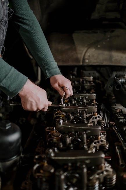
Spark Plug Inspection & Replacement
Regular spark plug inspection is crucial for maintaining optimal combustion in your Generac GP3300. Disconnect the spark plug wire and carefully remove the spark plug using a correctly sized socket wrench.
Inspect the spark plug for signs of wear, fouling, or damage. A healthy spark plug should have a tan or gray color. If the plug is blackened, oily, or exhibits electrode erosion, it requires replacement.
Gap the new spark plug to the manufacturer’s specification (refer to the technical specifications section). Install the new spark plug, tightening it to the recommended torque. Reconnect the spark plug wire securely.
Replace the spark plug every 100 hours of operation, or annually, whichever comes first. A properly functioning spark plug ensures efficient starting and smooth engine operation.

Fuel System Maintenance (Fuel Stabilizer)
To ensure the longevity of your Generac GP3300’s fuel system, especially during storage, utilizing a fuel stabilizer is highly recommended. Gasoline can degrade over time, leading to carburetor issues and starting difficulties.
Add fuel stabilizer to the gasoline tank whenever the generator will be stored for more than 30 days. Follow the stabilizer manufacturer’s instructions for the correct dosage. Run the generator for a few minutes after adding stabilizer to circulate it through the fuel system.
Old fuel can cause varnish buildup in the carburetor. If you suspect fuel degradation, drain the fuel tank and carburetor before adding fresh fuel. Always use fresh, high-quality gasoline.
Proper fuel maintenance prevents costly repairs and ensures reliable performance when you need it most. Regularly check for fuel leaks and address them immediately.
Troubleshooting Common Issues
This section addresses frequent problems encountered with the Generac GP3300. If your generator experiences issues, consult this guide before seeking professional assistance. Remember safety first – always disconnect the spark plug wire before performing any troubleshooting.
Generator Won’t Start: Check fuel level, ensure the fuel valve is open, and verify the spark plug is clean and properly gapped. A flooded engine may require a cold start procedure.
Low Power Output: Confirm the generator isn’t overloaded. Inspect the air filter for obstructions and ensure proper ventilation. Check the spark plug condition.
Overload Protection Tripping: Reduce the connected load. The GP3300 has a limited capacity; exceeding it triggers the breaker.
Unusual Noises: Investigate the source. Loose parts or a failing component may be the cause. Discontinue use and consult a qualified technician.
Generator Won’t Start
If your Generac GP3300 fails to start, systematically check several key components. First, verify sufficient fuel in the tank and ensure the fuel valve is in the ‘ON’ position. A clogged fuel line or carburetor can also prevent starting; consider using a fuel stabilizer for storage.
Next, inspect the spark plug. A fouled or damaged spark plug won’t ignite the fuel-air mixture. Clean or replace it, ensuring the correct gap is maintained. Confirm the spark plug wire is securely connected.
A flooded engine is another common cause. If you suspect flooding, allow the spark plug hole to dry before attempting a cold start. Finally, check the recoil starter mechanism for damage or binding.
Low Power Output
Experiencing low power output from your Generac GP3300 can stem from several issues. Overloading the generator is a primary cause; ensure the total wattage of connected appliances doesn’t exceed the GP3300’s rated capacity. Check each appliance’s wattage before connecting.
A dirty air filter restricts airflow to the engine, reducing efficiency. Regularly clean or replace the air filter as per the maintenance schedule. Low oil levels can also trigger a safety shutdown or reduce performance – always verify the oil level before operation.
Furthermore, a partially clogged fuel filter or carburetor can limit fuel delivery. Inspect and clean these components if necessary. Finally, ensure the spark plug is clean and properly gapped for optimal combustion.
Overload Protection Tripping
If the Generac GP3300’s overload protection is frequently tripping, it indicates the connected electrical load exceeds the generator’s capacity. This safety feature prevents damage to both the generator and your appliances. Immediately reduce the load by disconnecting non-essential devices.
Before restarting, carefully calculate the total wattage requirements of all remaining connected appliances. Ensure this sum remains within the GP3300’s rated wattage. Starting high-draw appliances (like air conditioners or refrigerators) simultaneously is a common cause of overload.
A faulty circuit breaker within the generator itself could also cause false tripping. If the issue persists with a reasonable load, professional inspection is recommended. Never attempt to bypass or disable the overload protection system;
Unusual Noises During Operation
Hearing unusual noises while running your Generac GP3300 warrants immediate attention. Rattling sounds could indicate loose components; carefully inspect the generator’s exterior for any visibly loose bolts or panels. A high-pitched squealing might suggest a worn or loose belt – do not operate if this is suspected.

Knocking sounds often point to internal engine issues, potentially related to lubrication or piston problems. Immediately shut down the generator and consult a qualified technician. Ignoring these sounds can lead to severe engine damage.
Normal operation includes engine noise, but it should be consistent. Changes in the sound’s pitch or intensity are cause for concern. Always prioritize safety and avoid attempting repairs yourself unless you are properly trained.

Generac GP3300 Parts Diagram
The Generac GP3300 Parts Diagram is an essential resource for maintenance, repair, and understanding the internal workings of your generator. This detailed schematic illustrates each component, from the engine assembly and recoil starter to the output receptacles and fuel tank.
Utilizing the diagram, you can accurately identify parts when ordering replacements, ensuring compatibility and a proper fit. It’s crucial for troubleshooting, allowing you to pinpoint the source of issues by visually tracing the system.
The diagram typically includes part numbers for easy ordering. Always refer to the latest version of the diagram, as updates may occur with model revisions. Proper identification of parts prevents incorrect installations and potential damage. A clear understanding of the diagram enhances your ability to maintain your Generac GP3300 effectively;
Technical Specifications

The Generac GP3300 boasts impressive technical capabilities. Its continuous output is 3000 watts, with a peak output reaching 3300 watts, providing reliable power for various applications. The engine is an 80cc, single-cylinder, four-stroke OHV engine, ensuring efficient operation.
Fuel capacity is 0.95 gallons, offering a runtime of approximately 8.9 hours at 25% load. It operates on unleaded gasoline. The generator weighs around 53.1 lbs, making it relatively portable. Noise level is rated at 60dB at 25% load, offering quieter operation.
Output receptacles include one 120V AC outlet and one 12V DC outlet. It features automatic voltage regulation (AVR) for stable power delivery. Dimensions are approximately 21.5 x 14.9 x 18.1 inches. Understanding these specifications is vital for safe and effective use.
Warranty Information
Generac provides a comprehensive warranty for the GP3300, offering peace of mind to its users. The standard consumer warranty covers defects in materials and workmanship for a period of one (1) year from the date of original purchase. This warranty applies to original purchasers and is non-transferable.
Commercial or rental use is typically covered by a separate, shorter warranty period, often 90 days. The warranty covers parts and labor necessary to repair or replace defective components. However, it does not cover damage resulting from misuse, abuse, neglect, accidents, or unauthorized modifications.
To make a warranty claim, you must contact an authorized Generac service dealer with proof of purchase. Keep your original receipt as evidence of the purchase date. Full warranty details, including exclusions and limitations, are available in the separate warranty document included with your generator.
Storage Guidelines
Proper storage is crucial for maintaining the Generac GP3300’s reliability. Before long-term storage, drain the fuel tank completely to prevent fuel degradation and carburetor issues. Run the generator until it stops from fuel starvation to empty the carburetor. Disconnect the spark plug wire for added safety.
Store the generator in a clean, dry, and well-ventilated area, protected from the elements. Cover the generator to prevent dust and debris accumulation. Avoid storing it near flammable materials. Consider using a fuel stabilizer if complete fuel drainage isn’t possible, following the stabilizer’s instructions carefully.
Periodically check the generator during storage. Before restarting after storage, check the oil level and add if necessary. Inspect all cables and connections for damage. Following these guidelines will ensure your GP3300 is ready when you need it.
Frequently Asked Questions (FAQ)
Q: How often should I change the oil? A: Refer to the maintenance schedule, but generally, every 50-100 hours of operation, or at least once a year.
Q: What type of oil is recommended? A: Use SAE 10W-30 oil, meeting API service classification SJ or higher.
Q: Why won’t my generator start? A: Check fuel levels, the spark plug, and ensure the choke is properly set. A faulty recoil starter can also be the cause;
Q: What does the overload light indicate? A: It means you’re drawing more power than the generator can handle. Reduce the load by disconnecting appliances.
Q: Can I run this generator in the rain? A: The GP3300 is designed for outdoor use, but avoid direct exposure to heavy rain. Always ensure proper ventilation.